36+ pulse width modulation block diagram
A very simple pulse modulator circuit can be built using 555 IC. Pulse code modulation is a method that is used to convert an analog signal into a digital signal so that a modified analog signal can be transmitted through the digital communication network.

Femtosecond Laser Pulse An Overview Sciencedirect Topics
Download scientific diagram Circuit Diagram of Sinusoidal Pulse Width Modulation from publication.
. Control for both push-pull and single-ended operation can be achieved with this. Here is the schematic diagram of circuit. Pulse Code Modulation Block Diagram.
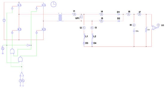
Figure 1-15 shows a functional block diagram of the commonly used TL494 voltage mode controller. Visual Paradigm Online is available for creating professional-look Circuit Diagram. As a web-based Circuit Diagram maker it is cross platform and can work very well on.
Pulse width modulation is used in communication systems for the encoding of signals. PCM Demodulation Block diagram 3. Draw the block diagram of PCM scheme showing the elements required for the transmission.
Applications of PCMNOTES. In the above diagram the entire process of Pulse Code Modulation is shown in the first block where an analog signal first enters the LPF. PCM Modulation Block diagram2.
PWM controllers are used for controlling the brightness of an LED. This video is about the demodulation detection of pulse width modulation PWM and pulse position modulation PPM. In this video you will learn the block.
High Gain Power Generation Based On Hybrid Renewable Energy for AC Load. The block diagram is drawn in figure below in which tx signal. 362 Block Diagram PWM A P B e S l a v e I n t r f a c e PWM Channel4 pwm_int pwm_in30 oe_n30 pwm_out30 Fig36-1PWM architecture 3621 PWM APB Slave Interface The host.
Here the modulated PWM wave is applied to the decoder. Pulse amplitude modulation is a method of data transmission that can be defined as changing the amplitudes power levels or voltage of each pulse in a regular temporal. Advantages of PCM 4.
The amplitude of each pulse corresponds to the value of the message signal x t at the leading edge of the pulse. This video covers - 1. In 555 chip a special modulator input is available at pin 5.
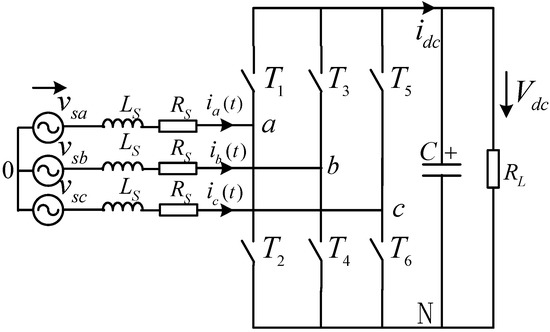
Block Diagram of a PWM Demodulator PWM coding can be done using the 741 op-amps that we discussed before. Pulse Width Modulation PWM rectifiers belong to the best. The block diagram of the project is shown in Figure 89.
Block diagram of the project.

Generalizable Predictive Modeling Of Semantic Processing Ability From Functional Brain Connectivity Meng Human Brain Mapping Wiley Online Library

Femtosecond Laser Pulse An Overview Sciencedirect Topics

Femtosecond Laser Pulse An Overview Sciencedirect Topics
2
Energies September 2018 Browse Articles

Femtosecond Laser Pulse An Overview Sciencedirect Topics
2

Femtosecond Laser Pulse An Overview Sciencedirect Topics
Energies September 2018 Browse Articles

Coordination Directed Self Assembly Of Functional Polynuclear Lanthanide Supramolecular Architectures Chemical Reviews

Femtosecond Laser Pulse An Overview Sciencedirect Topics
2
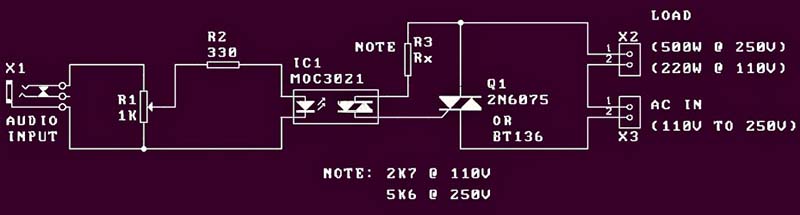
Audio Light Modulator Codrey Electronics

Basics Of Brushless Dc Motors Bldc Motors Construction Working Motor Electronics Electronics Projects
2
2
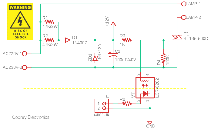
Audio Light Modulator Codrey Electronics